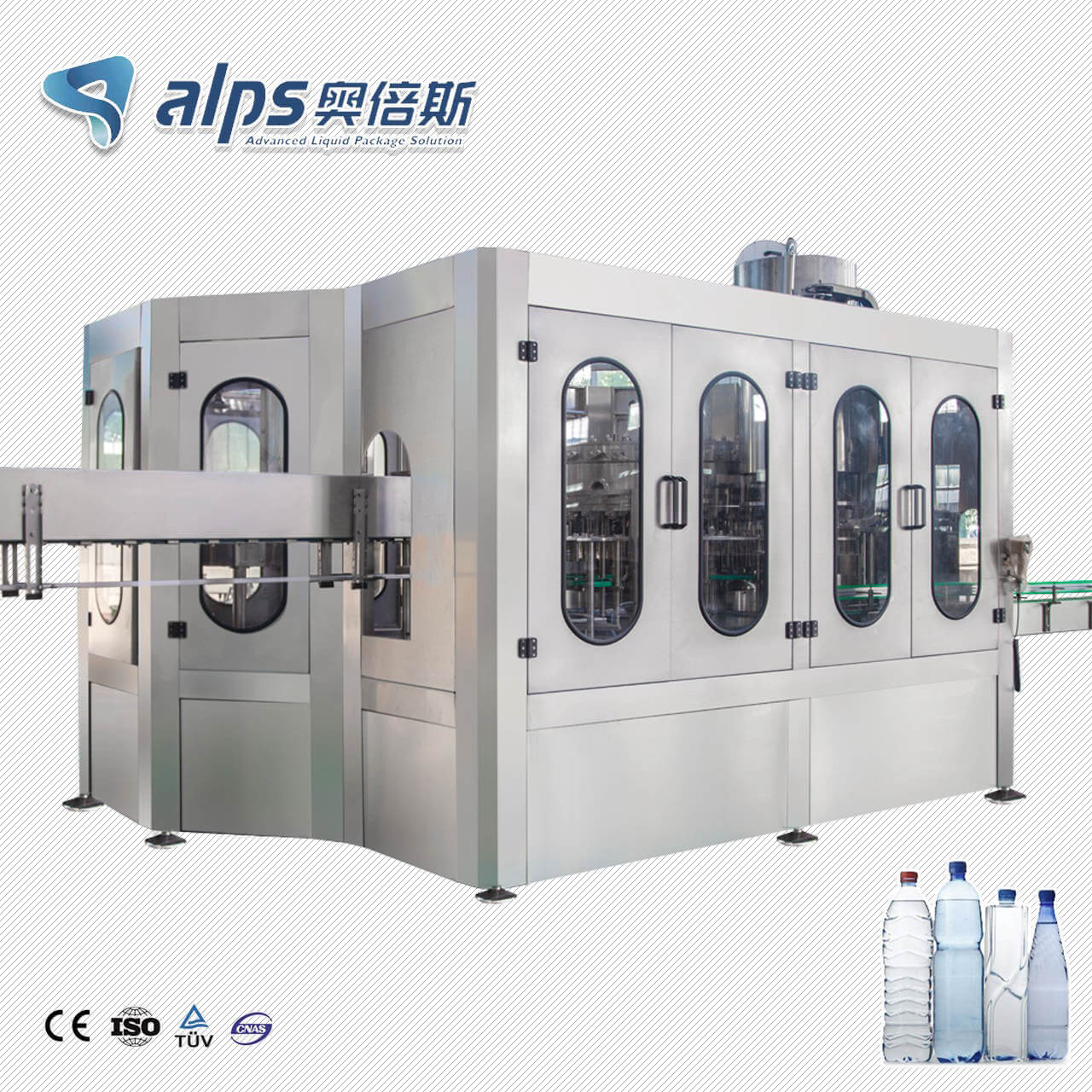
A water filling line can meet its speed specification and still fail to run reliably if the site cannot supply stable power, compressed air, treated water, or drainage at the required conditions. Utility planning must therefore begin before the equipment layout and building services are finalized, not after machines arrive.
There is no universal utility figure for every bottling line. Requirements change with the equipment scope, bottle formats, PET blowing method, water-treatment process, cleaning regime, packaging system, and local electrical and sanitation rules. The correct deliverable is a project-specific utility schedule tied to the final equipment list and points of connection.
Start with a Clear Utility Design Basis
Before adding loads, freeze the commercial and technical basis: target BPH by bottle size, products, shift pattern, line boundary, cleaning method, ambient conditions, and expansion scenario. Capacity calculations belong in the separate capacity guide; here, the target rate is an input used to determine simultaneous utility demand.
Ask each supplier to state values at the agreed machine boundary. A plant-level total is only useful when every item uses the same units, pressure reference, operating condition, and demand definition.
Utility | Typical consumers | What must be specified | Frequent omission |
Electrical power | Blower, filler, conveyors, labeler, packer, pumps | Voltage, phase, frequency, connected load, operating and peak demand | Auxiliaries and starting demand |
Compressed air | Pneumatic actuators, air conveyor, cap and pack equipment | Pressure, normal and peak flow, quality, duty cycle | Separate PET blowing air |
Water | Product, rinse, treatment, cleaning, cooling and service users | Source quality, pressure, temperature, normal and peak flow | Treatment losses and cleaning demand |
Drainage | Rinser, CIP, floor wash, treatment reject and condensate | Peak flow, temperature, chemistry, connection and disposal route | Simultaneous discharge events |
Electrical Power Requirements
List the voltage, frequency, number of phases, permitted tolerance, earthing arrangement, short-circuit information, and required disconnect for every machine. Imported equipment must be checked against the actual site supply; a nominal voltage match does not prove that the protection, motor ratings, controls, or transformer arrangement are suitable.
IEC 60204-1 covers electrical, electronic, and programmable equipment for machines from the point where the supply connects to the machine. The project electrical engineer must also apply the destination country's codes, utility-provider rules, and site safety requirements.
Keep three numbers separate. Connected load is the sum of installed nameplate ratings. Expected operating demand reflects which loads normally run and at what duty. Peak demand includes credible simultaneous operation and starting events. Using connected load as energy consumption overstates the bill, while using an average demand to size feeders or transformers can create trips and voltage drop.
The equipment list should include motors and heaters inside the main machines, plus water-treatment pumps, air compressors, chillers if used, conveyors, coding equipment, inspection devices, extraction, lighting, and workshop services. State clearly whether the supplier or plant owner provides local isolators, cabling, cable trays, distribution panels, and final connections.
Compressed Air Requirements
Compressed air must be scheduled by pressure, flow, quality, and duty cycle. A single plant-wide CFM or m³/min figure is incomplete. Pneumatic cylinders may have intermittent peaks, while an air conveyor or process-air user may create a different demand profile. Record normal flow, maximum credible flow, minimum pressure at the point of use, and the reference condition used for flow data.
If PET bottles are blown on site, do not combine bottle-blowing air with general machine air without analysis. Stretch blow molding commonly uses a separate high-pressure system, while the filler, labeler, packer, valves, and actuators use lower-pressure service air. The compressor package, receiver, dryer, filters, ring main, and pressure losses must be evaluated for each pressure level.
Specify air quality at the point of use.
ISO 8573-1 defines compressed-air purity classes for particles, water, and oil and also identifies gaseous and microbiological contaminants. It does not select one universal class for all beverage applications; the required class depends on whether air contacts product, containers, closures, or only non-product pneumatic components.
A useful compressor review also covers ambient temperature and altitude, standby philosophy, dryer pressure dew point, condensate disposal, leak allowance, and future additions. Reserve capacity should follow a documented expansion or reliability case rather than an arbitrary percentage.
Water Supply and Treatment Demand
Separate raw source water, treated product water, bottle-rinse water, cleaning or CIP water, cooling water, and general service water. They may require different quality, temperature, pressure, storage, and piping materials. Combining them in one headline flow rate hides both hygiene risks and short-duration peaks.
Base product-water flow (L/h) = bottles per hour × nominal fill volume (L/bottle)
This base flow is only the water entering saleable bottles. The treatment system must also account for process recovery, filter backwash or regeneration, membrane reject, sanitization, bottle rinsing, start-up and changeover losses, tank operating level, and any simultaneous cleaning demand. Do not apply an unverified recovery factor: raw-water analysis and the selected treatment process determine the design.
Review the complete
bottled water production process to identify where product water, rinse water, and service water are consumed. Then issue separate values for normal production, peak use, cleaning, and non-production periods so storage tanks and supply pumps can be sized against the real operating sequence.
For U.S. bottled-water operations,
21 CFR Part 129 addresses processing and bottling practices, including product-water and operational-water considerations. Other markets have their own food-safety, plumbing, and wastewater rules, so the final design requires local regulatory review.
Drainage Requirements
Drainage should be sized for the highest credible simultaneous discharge, not the average water consumption of a shift. Consider rinser discharge, CIP dump and final rinse, floor washing, water-treatment reject or backwash, compressor condensate, equipment drains, and emergency or maintenance emptying. Record flow, duration, temperature, chemistry, solids, and whether neutralization or other treatment is required before disposal.
Connection positions must be coordinated with the water bottling plant layout . Drain channels, floor slopes, cleanable access, and wet-area boundaries affect machine placement and pedestrian routes. Keep process wastewater, sanitary sewage, and stormwater separated as required by local code, and prevent drain routes from creating contamination or backflow risks.
Build an Engineering Utility Schedule
The schedule should be a controlled project document, not a collection of numbers copied from brochures. Give every machine and auxiliary a unique tag, identify the source of each value, and revise the total whenever the equipment scope or operating sequence changes.
Required field | Why it matters |
Equipment tag and service | Prevents omitted or double-counted loads |
Utility and units | Keeps power, air, water, thermal and drainage data comparable |
Normal, peak and connected values | Supports operating cost and infrastructure sizing |
Pressure, temperature and quality | Defines usable conditions at the machine |
Duty cycle and simultaneous-use group | Shows which peaks can occur together |
Connection size and point of connection | Coordinates building services with the layout |
Supplier/owner scope and source document | Makes responsibilities and revisions auditable |
After individual entries are complete, prepare separate plant summaries for normal production, start-up, cleaning, and maximum credible simultaneous operation. This is more defensible than adding every nameplate maximum, and safer than sizing from an average shift value.
Common Utility Planning Mistakes
Treating one supplier total as final. Check whether it includes water treatment, blow molding, compressors, chillers, conveyors, labeling, packing, inspection, and plant services.
Confusing connected load with consumption. Use connected and peak values for infrastructure studies, and duty-based operating demand for energy estimates.
Ignoring simultaneous peaks. A CIP dump, filter backwash, compressor recovery, and production start may overlap even when their daily averages look small.
Merging all compressed-air users. Separate pressure levels, air-quality needs, and high-pressure PET blowing demand.
Sizing water from bottle volume alone. Add treatment losses, rinsing, sanitation, service demand, and storage strategy using verified project data.
Routing drains after equipment is fixed. Late changes can compromise floor levels, hygienic zoning, access, and wastewater compliance.
Verify Utilities Before Final Acceptance
Factory acceptance can confirm drawings, nameplates, component ratings, control logic, and the supplier's stated utility data. It cannot prove that the buyer's building will deliver the required voltage, pressure, flow, quality, or drainage capacity at every machine.
During commissioning, record
site utility checks during SAT under agreed production conditions. Measure at the point of connection while relevant users run simultaneously, and define the instrument, acceptance limit, test duration, and party responsible for correction before the test begins.
Utility Information Buyers Should Request
Before approving the line and site-services design, request:
A final equipment list and revision-controlled utility schedule.
Electrical single-line requirements, load list, and machine connection data.
Compressed-air pressure, normal and peak flow, purity requirement, and duty cycle by user.
Raw, product, rinse, cleaning, cooling, and service-water demand by operating mode.
Drain flow, temperature, chemistry, duration, and connection location for every source.
A layout showing all owner-supplied utility points and the supplier's battery limits.
Commissioning procedures and acceptance criteria for site utility verification.
For a new facility, include utility connections, wastewater handling, and local approvals in the broader plan for starting a bottled water business. A technically suitable line can still become a poor investment if the building-services scope is underestimated or assigned ambiguously.
Frequently Asked Questions
Can a supplier give one standard utility figure for a water filling line?
Only as an early estimate tied to a stated configuration. Final requirements depend on bottle formats, line speed, equipment brands, water treatment, PET blowing, cleaning, packaging, ambient conditions, and local standards. Buyers should not release building-services design from a generic brochure value.
What is the difference between connected load and operating load?
Connected load is the sum of installed electrical ratings. Operating load estimates what normally runs and at what duty, while peak demand represents the highest credible simultaneous requirement. Each serves a different purpose in feeder, transformer, generator, and energy-cost studies.
Should PET bottle blowing air be included in general compressed air?
It must be included in the plant study but normally shown as a separate pressure service. Blow molding can require a different compressor, receiver, dryer, filtration arrangement, and piping network from lower-pressure machine air. Combining the totals without pressure data is not valid.
How should drainage capacity be estimated?
Create a discharge schedule for every source, including flow, duration, temperature, chemistry, and operating sequence. Group events that can occur together and size the local branches and main system for the resulting peak, subject to local plumbing and wastewater requirements.
How much spare utility capacity should a new plant reserve?
There is no universal percentage. Base reserve on a defined second shift, extra SKU, future machine, standby requirement, or forecast expansion phase. Document which future loads are included so the project does not pay for undefined capacity or block a planned upgrade.
Conclusion
Reliable water filling line utilities are defined by conditions, operating modes, and connection points—not by four headline totals. Separate connected, normal, and peak demand; distinguish pressure and quality levels; account for treatment and cleaning losses; and size drainage for credible simultaneous discharge. A revision-controlled utility schedule gives purchasing, equipment suppliers, and site engineers one basis for design and acceptance.
To prepare a project-specific utility schedule, provide the bottle range, target BPH, water analysis, equipment scope, shift and cleaning plan, site voltage, ambient conditions, and preliminary building layout. These inputs allow the turnkey line and plant services to be coordinated before installation changes become expensive.