Advanced Liquid Package Solution
Any question?
Get in touch


A workable water bottling plant layout does more than fit machines inside a building. It protects exposed product, gives operators and maintenance staff room to work, and moves materials from receiving to dispatch without avoidable crossings.
Start with the process and the tasks around it, then position the equipment. Machine footprints alone will not reveal a blocked access door, a cap-delivery route through the filling area, or a packing pallet that obstructs a drain. This guide focuses on still-water PET bottling; returnable-container and aseptic operations need additional, process-specific review.
Collect a measured building drawing showing columns, door openings, ceiling heights, floor levels, loading access and existing services. Obtain each supplier's general arrangement (GA) drawing, including conveyor entry and exit positions, operating sides, guards, access doors and component-removal requirements.
Confirm whether the project includes water treatment, on-site PET blowing, purchased empty-bottle storage, labeling, packing, palletizing and finished-goods storage. Two lines with the same BPH can need very different buildings if one stores purchased bottles while the other blows preforms on site.
Set storage quantities from delivery frequency, shift demand and dispatch arrangements, not leftover floor space. For the broader investment and site-selection decisions, see how to start a bottled water business. Here, those decisions become inputs to the physical layout.
For a conventional still-water PET line, a starting sequence is bottle supply, rinsing where specified, filling, capping, inspection, labeling and coding, packing, then palletizing and dispatch. Treated water reaches the filler through the sanitary product-water system, while closures enter through their own controlled supply route. Use the bottled water production process guide to check the equipment scope before arranging it.
Draw the product route first, then overlay the movements that keep it running:
• People: entry, hand hygiene and changing points, operating stations, sampling and access between zones.
• Packaging: preforms or empty bottles, caps, labels, film and cartons from storage to their replenishment points.
• Waste: rejected bottles, empty packaging and cleaning waste moving to collection without passing through exposed-product areas.
• Maintenance: tools, service carts and removed parts reaching the machine without using production space as temporary storage.
A straight product arrow is not enough if these routes repeatedly cross it. Identify each crossing and decide whether to relocate the activity, separate the routes or introduce a controlled transfer point.

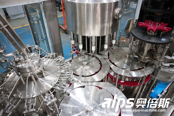
Rinsing, filling and capping sections connected by transfer starwheels. This equipment view illustrates internal product transfer, not the surrounding factory layout.
The European packaged-water hygiene guide, hosted by the European Commission, connects layout with contamination prevention, cleanability and the movement of materials and personnel. Use it as sector guidance, not as a substitute for destination-market requirements or the plant's hazard assessment.
For layout planning, identify where rinsed bottle interiors, water and the inside surfaces of closures are exposed. These points generally need tighter controls than operations handling sealed bottles. Ask the food-safety team to define the boundaries, entry conditions and permitted activities before walls and doors are fixed.
Area | What needs attention | Layout decision |
Receiving and storage | Outer packaging; incoming materials | Protected stock; controlled unpacking point |
Water treatment | Tanks, treatment skids and service tasks | Sanitary transfer; service-side access |
Rinsing, filling and capping | Rinsed bottles, water and closure interiors | Controlled entry; protected transfer points |
Labeling and packing | Sealed bottles; labels, film and cartons | Replenishment and rejects outside filling zone |
Support and waste | Tools, chemicals, rubbish and maintenance | Dedicated storage and removal routes |
Treat this zoning table as a planning worksheet, not a prescribed room classification. Physical partitions, controlled access, protected transfers and airflow measures should follow the assessed contamination risks. A machine enclosure does not by itself establish a cleanroom, and a cleanroom label does not prove the filling process is aseptic.
Pay particular attention to transitions: where cap bags are opened, where bottles enter the filling enclosure, and where personnel leave packing to attend the filler. Define what may cross each boundary and how it is handled.
There is no single clearance that suits every filler, labeler or packer. Ask suppliers to mark four working spaces around each machine, then check where they overlap:
• Operation and replenishment: standing positions, control-panel access, cap loading, reel changes and routine adjustment.
• Cleaning: access to surfaces, safe use and storage of cleaning equipment, and drain inspection without dismantling unrelated machinery.
• Maintenance and removal: fully opened guards, electrical-cabinet doors, lifting equipment, and the path for removing motors, valves or larger assemblies.
• Safety and logistics: pedestrian passage, material-handling routes, emergency access and required electrical working space.
A gap that is adequate for walking may be inadequate for replacing a drive motor. Likewise, two facing access doors can each meet their supplier's individual drawing yet collide when opened together. Resolve these cases on the combined plant layout.
Check height as well as floor area: lifted components, cap elevators, overhead conveyors and pipework may conflict with beams or building services. Final dimensions must follow the equipment documentation and the applicable local safety, electrical and building requirements.

Open guard doors and detached panels show why access extends beyond the machine frame. This equipment-access photo is not a model of an approved operating layout.
A straight arrangement can make process direction and zone boundaries easy to follow, but it may require a long building. An L-shaped arrangement can work around columns or separate packing from filling. A U-shaped arrangement can suit some logistics plans, but nearby infeed and outfeed areas may create competing material routes. Compare the actual movements rather than selecting a shape by preference.
Mark accumulation areas deliberately. Check the bottle condition, conveyor access, discharge direction and space needed to clear a blockage safely. Keep buffer footprints and pallet staging out of required aisles and service spaces.
The physical arrangement must support balancing a complete water filling line . Speed matching and buffer-capacity calculations belong in that guide; the layout must reserve usable space for the agreed solution.
Show connection locations and elevations on the same drawing as the machines. Review power, air, water and drainage requirements [Internal link pending → Article 02: Water Filling Line Utility Requirements: Power, Air, Water and Drainage] before fixing service routes. Utility loads are separate calculations; this review checks whether the connections can be installed, reached and maintained.
Coordinate wet-area drainage, floor levels and machine feet before construction. Keep drain-cleaning access visible on the drawing, and check whether hoses or temporary connections would cross walkways. Locate pipe supports, cable trays and isolation points so they do not obstruct guards, maintenance lifts or cleaning. Have process, building-services and food-safety specialists review the interfaces together.
Test the drawing with ordinary tasks, not only normal production. Trace a cap delivery, label-reel change, rejected-bottle removal, planned cleaning task and major component replacement. Then test the same routes while packing materials and finished pallets are being moved.
For an existing building, a floor-marking walkthrough can expose conflicts that are easy to miss on screen. Include production, maintenance, quality, logistics and the equipment supplier. Record each unresolved issue with an owner and a drawing revision; do not rely on verbal agreement.
Hygienic review and statutory safety review are different approvals. The published scope of EHEDG Guideline 44 on hygienic factory design explicitly excludes national and international building and safety standards, including fire standards. Obtain the relevant local design checks separately.
Before release, the coordinated drawing should identify equipment tags, dimensions, zone boundaries, personnel and material routes, connection points, service spaces and a defined expansion option. Future equipment needs a delivery route and connections as well as an empty rectangle.
There is no reliable universal area-per-BPH rule. Build the requirement from equipment drawings, working spaces, utilities, storage and circulation, then test it against the building's shape and constraints. Ask whether a quoted area covers only the line or the entire operation.
Do not specify a cleanroom solely from the machine speed or bottle size. The product, filling method, exposure points, hazard assessment and local requirements determine the environmental controls; a conventional still-water layout should not automatically inherit an aseptic-room specification.
Possibly, if the risk assessment and local requirements allow a controlled arrangement. Distinguish protected primary packaging from outer cartons and pallet traffic, and define unpacking, replenishment and waste-removal points so storage does not undermine the filling-zone controls.
Reserve space against a defined equipment concept, including delivery access, operating and service areas, material routes and utility connections. Also consider how installation work could be separated from ongoing production; unused floor area alone does not establish expansion readiness.
Before approving a water bottling plant layout, ask the team to demonstrate how the line will be supplied, operated, cleaned and repaired. A drawing that supports those tasks provides a stronger basis for purchasing than machine footprints alone. Share the building plan, bottle formats, equipment scope and storage assumptions with Alps Machine to discuss a coordinated line arrangement.


By continuing to use the site you agree to our privacy policy Terms and Conditions.