Advanced Liquid Package Solution
Any question?
Get in touch


Water treatment plant construction for a bottled water project begins with a verified raw-water profile and a written product-water target. Those inputs determine the treatment train, building interfaces, utilities, waste streams and acceptance tests. Choosing equipment before the design basis is clear usually creates changes during installation or commissioning.
This guide follows the project from initial data collection through handover. It focuses on water treatment inside a beverage plant, including the connection to purified-water storage and the filling line. Municipal distribution networks and wastewater treatment plants require different permitting, civil works and process expertise and are outside this article's scope.

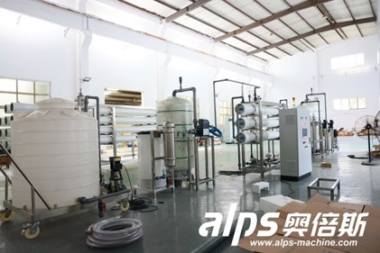
The treatment process, access routes, pipework and controls need to be planned as one operating area. Source ALPS Machinery
The construction scope is wider than buying filters or a reverse osmosis skid. A complete project may include a source-water connection, raw-water storage, pretreatment, the main purification stage, post-treatment, product-water storage, disinfection, transfer piping, concentrate or backwash handling, electrical distribution, controls and sampling points. The exact boundary must be stated before suppliers prepare quotations.
The reference article supplied for this project organizes the work into needs assessment, site selection, design, construction, commissioning and operation. That sequence is sound. For a beverage factory, each phase also needs an interface with production demand, hygienic storage and the filling schedule.
Phase | Main decision | Required output |
1. Design basis | Define source water, product water, demand and applicable rules | Approved input data and project boundary |
2. Concept design | Select the treatment route and estimate utilities, space and waste streams | Process flow and preliminary layout |
3. Detailed design | Coordinate equipment, tanks, piping, electrical work and controls | Approved drawings, specifications and interface list |
4. Procurement and site work | Order equipment while foundations, drains and utility connections are prepared | Released vendor documents and construction plan |
5. Installation | Set, connect and inspect equipment and instruments | Mechanical completion and punch list |
6. Commissioning | Flush, sanitize, start and test the integrated system | Performance records and acceptance result |
7. Handover | Transfer operating procedures, training, spares and maintenance information | Controlled turnover package |
Source-water quality has a direct effect on treatment operation. The US EPA notes that geology, land use and activity in the watershed or wellhead area can change source quality. Collect representative laboratory results and identify seasonal or operational variation instead of designing from one convenient sample.
The finished-water specification is equally important. State the product category, target parameters, sampling method and governing market requirements. In the United States, FDA bottled-water rules cover source and finished-product testing, sanitary processing and plant design. Other markets may apply different product, drinking-water, food-safety and environmental requirements, so the project team must confirm the local basis before detailed design.
Capacity should be expressed as a water balance rather than as a filler speed alone. The calculation needs production volume by shift, peak demand, tank turnover, cleaning demand, filter backwash or regeneration, membrane recovery, planned downtime and future formats. This separates product-water demand from raw-water feed and prevents a nominal machine rating from becoming the plant design basis by accident.
Design input | What to provide | Why it changes construction |
Raw-water report | Representative physical, chemical and microbiological results | Sets pretreatment, membrane, disinfection and residuals needs |
Finished-water target | Product identity, limits, test methods and sampling points | Defines the treatment objective and acceptance criteria |
Production demand | Hourly peak, daily volume, shifts, cleaning windows and growth | Sizes treatment, storage and transfer capacity |
Site and utilities | Available area, power, water, drains, ventilation and access | Controls layout, service connections and civil scope |
Waste routes | Backwash, concentrate, spent media and chemical handling | Affects drains, tanks, permits and operating cost |

A membrane system still depends on suitable pretreatment, feed conditions, utilities and a managed concentrate route. Source ALPS Machinery
Treatment stages follow the contaminants and the required water quality. The CDC overview of drinking-water treatment describes coagulation, flocculation, sedimentation, filtration and disinfection as common utility steps. The EPA technology overview also covers adsorption, ion exchange, reverse osmosis, nanofiltration and advanced oxidation. A bottled-water project uses only the stages justified by its source and product specification.
Reverse osmosis is not an automatic starting point for every source. It can remove a broad range of dissolved contaminants, but it also creates a concentrate stream, uses pressure and may require pretreatment and post-treatment. Ultrafiltration, media filtration, activated carbon, softening, dosing, UV or ozone may be used in different combinations. Pilot work or sample testing may be appropriate when the feed varies or treatment performance is uncertain.
ALPS publishes a separate bottled-water treatment process guide and a complete process-flow article. Those pages should remain the detailed owners of treatment-stage selection. This construction guide uses the process train only to define space, utilities, interfaces and testing.
A workable layout separates raw-water activities from the treated-water side and gives operators a clear route through the process. Tanks, pumps, filters, membrane skids, chemical systems and control panels need access for inspection and removal. Door openings, lifting paths, cartridge change space and membrane extraction clearance should be checked on the general arrangement, not discovered after walls or pipe racks are complete.
The hydraulic profile affects pump duty, tank elevations and pipe routing. The design also needs floor slopes and drains, bunding or secondary containment where required, ventilation for chemical or ozone areas, washdown access, lighting and safe electrical locations. Reserve realistic space for future expansion only when it is part of the business plan; an unlabeled empty area is not an expansion strategy.

Tank connections, drainability, valve access and service clearance should be resolved on the layout before installation. Source ALPS Machinery
Civil drawings must carry the loads and anchor details supplied by the equipment vendors. They also define equipment pads, openings, trenches, curbs, drains and any chemical containment. Mechanical design connects the process through tanks, pumps, valves and pipework while preserving access, cleanability and the intended hydraulic conditions.
Electrical and control work links the installed equipment into an operable plant. Confirm power characteristics, motor control, panel locations, cable routes, earthing, emergency stops and backup needs. The instrumentation list should identify flow, pressure, level, conductivity, turbidity or other project-specific measurements, together with alarm limits, calibration responsibility and data-recording requirements.
The purified-water outlet is an important battery limit. Define the storage tank, recirculation loop, final disinfection, transfer pressure, pipe material, hold time and connection to the filler. ALPS discusses the different roles of UV and ozone in a dedicated guide, so this article does not repeat the full disinfection comparison.
Interface | Confirm before release | Evidence at handover |
Civil to equipment | Loads, anchors, pads, openings, drainage and access | As-built dimensions and installation inspection |
Mechanical to process | Pipe sizes, materials, valves, slopes, vents and sampling points | Pressure or leak tests and line identification |
Electrical to equipment | Supply, load list, protection, panels, cables and emergency stops | Test records and approved schematics |
Controls to operation | I/O list, alarms, interlocks, recipes, trends and permissions | Loop checks, alarm tests and backups |
Treatment to filling | Water quality, flow, pressure, storage, disinfection and hygiene boundary | Integrated water trial and product-water results |
Release major equipment after the design basis, process flow, preliminary layout, utility data and battery limits have been reviewed together. Vendor drawings then feed the foundations, building openings, pipe racks, electrical rooms and installation plan. A late change to a tank connection or membrane skid can move several construction packages, so document reviews need named owners and due dates.
Factory acceptance testing should match the equipment that can be tested before shipment. Site installation checks cover equipment identity, damage, level and alignment, supports, valve orientation, instrument location, piping cleanliness, electrical termination, I/O and drainage. Keep a controlled punch list rather than treating incomplete work as a commissioning problem.
ALPS presents reverse osmosis, ultrafiltration, media filtration, UV and ozone equipment within its water treatment system range. Its mineral-water production-line page also places water treatment upstream of bottle making, filling and packaging. The quotation should state whether the offered scope stops at equipment supply or includes layout, installation supervision, commissioning and line integration.

Each treatment module needs confirmed feed conditions, service access, utility connections and acceptance criteria. Source ALPS Machinery
Commissioning starts after mechanical completion and documented safety checks. The usual sequence includes dry rotation and electrical checks, instrument calibration, piping flushes, cleaning or sanitization, water introduction, individual equipment startup and integrated operation. The project-specific procedure should define who may authorize each step and how deviations are recorded.
Acceptance needs both operational and compliance evidence. WHO drinking-water guidance distinguishes operational monitoring, which shows whether control measures are working, from verification of the finished supply. For a bottled-water project, the test plan should likewise separate live process measurements from approved laboratory results for the product-water specification.
Acceptance area | Typical evidence |
Mechanical completion | Signed inspections, punch-list status, line identification and pressure or leak records |
Controls and safety | I/O checks, alarm and interlock tests, emergency-stop checks and parameter backups |
Water quantity | Sustained flow and storage performance under the agreed operating condition |
Water quality | Sampling records and laboratory results at defined locations and operating conditions |
Cleaning and sanitation | Approved procedure, completed cycle records and release criteria |
Handover | As-built drawings, manuals, training records, spare-parts list and maintenance plan |
A useful budget separates process equipment from tanks and civil work, piping, electrical and controls, utility upgrades, waste handling, installation, engineering, permits, freight, taxes and contingency. Operating cost depends on energy, chemicals, membrane or media replacement, labor, monitoring, cleaning and disposal. A generic price per unit of flow hides these boundaries and should not be used as a quotation.
The EPA work-breakdown cost models show why preliminary estimates combine equipment, buildings, site work, piping, wiring, engineering and other indirect items. Actual commercial pricing still requires current project data and local quotations.
Schedule is shaped by laboratory work, permits, design reviews, long-lead equipment, civil readiness, utility tie-ins, shipping, customs and the water trial. Track the dependencies instead of assigning one duration to all plant sizes. Commissioning should have enough time for adjustment and repeat testing before production commitments begin.
A supplier can prepare a clearer proposal when the request includes the following information.
· Raw-water source, representative laboratory report and expected variation.
· Finished-water specification, product category, destination market and required test methods.
· Hourly and daily demand, production schedule, cleaning demand, storage strategy and growth plan.
· Site plan, available room dimensions, access limits, floor and drainage information and climate conditions.
· Available power, feed-water pressure, compressed air, chemicals, ventilation and waste-disposal routes.
· Required redundancy, automation, data records, remote support and operator-permission levels.
· Scope boundary for tanks, pipes, electrical work, civil work, installation, commissioning and training.
· FAT and SAT conditions, sampling plan, acceptance limits, documentation and spare-parts requirements.
Water treatment plant construction stays manageable when the team fixes the design basis before it fixes the building or equipment list. Start with the water analysis, product-water target and production balance. Then ask suppliers to show how the proposed process, layout, utilities, waste routes and acceptance tests fit the same duty.
Use those inputs to review the ALPS water treatment system range and send the project boundary through the ALPS contact page for configuration discussion.
There is no reliable universal duration. The schedule depends on the completeness of the water analysis, permitting, design reviews, equipment lead times, civil scope, site utilities, shipping, installation and performance testing. Ask for a logic-linked schedule with owner and supplier milestones rather than a single delivery promise.
Cost cannot be estimated from capacity alone. Source-water quality, finished-water limits, recovery, redundancy, storage, building work, utilities, controls, waste handling, local labor and the supply boundary all change the budget. Compare quotations only after those assumptions and exclusions are listed on the same basis.
Begin with a representative raw-water analysis and a written finished-water specification. Add the production water balance and applicable market requirements. These inputs allow the engineer and equipment supplier to select a treatment route and define the project boundary.
No. Reverse osmosis is selected when the source and product target justify membrane desalting or broad dissolved-contaminant removal. Some projects use other filtration, adsorption, softening, ultrafiltration or disinfection combinations. The decision should follow testing and regulatory review, not a standard equipment package.
The equipment footprint is only part of the answer. The layout also needs tanks, pipe routes, control panels, chemical areas, drains, maintenance access, membrane or media replacement paths and safe operator movement. Expansion space should be tied to a defined future stage and protected from later use.
Test equipment rotation, instruments, alarms, interlocks, valves, leaks, cleaning and sanitation before the performance run. The integrated test should then verify water quantity and quality at defined conditions, together with storage and transfer to the filler. Record sampling locations, methods, duration and pass or fail limits in advance.
No. A bottled-water treatment plant conditions a source for a food product and transfers treated water into hygienic storage and filling. A wastewater plant treats a spent stream for discharge or reuse. The permits, biological processes, residuals and civil scope can differ substantially, so wastewater contractor keywords should not be treated as equivalent intent.


By continuing to use the site you agree to our privacy policy Terms and Conditions.