Advanced Liquid Package Solution
Any question?
Get in touch


Water treatment plant construction for a bottled water project begins with a verified raw-water profile and a written product-water target. Those inputs determine the treatment train, building interfaces, utilities, waste streams and acceptance tests. Choosing equipment before the design basis is clear usually creates changes during installation or commissioning.
This guide follows the project from initial data collection through handover. It focuses on water treatment inside a beverage plant, including the connection to purified-water storage and the filling line. Municipal distribution networks and wastewater treatment plants require different permitting, civil works and process expertise and are outside this article's scope.

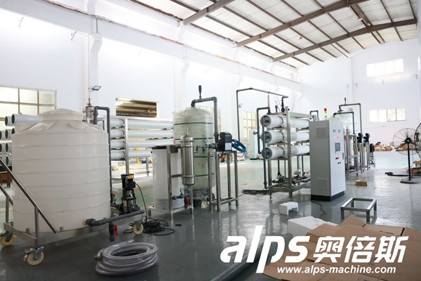
The treatment process, access routes, pipework and controls need to be planned as one operating area. Source ALPS Machinery
The construction scope is wider than buying filters or a reverse osmosis skid. A complete project may include a source-water connection, raw-water storage, pretreatment, the main purification stage, post-treatment, product-water storage, disinfection, transfer piping, concentrate or backwash handling, electrical distribution, controls and sampling points. The exact boundary must be stated before suppliers prepare quotations.
The reference article supplied for this project organizes the work into needs assessment, site selection, design, construction, commissioning and operation. That sequence is sound. For a beverage factory, each phase also needs an interface with production demand, hygienic storage and the filling schedule.
Phase | Main decision | Required output |
1. Design basis | Define source water, product water, demand and applicable rules | Approved input data and project boundary |
2. Concept design | Select the treatment route and estimate utilities, space and waste streams | Process flow and preliminary layout |
3. Detailed design | Coordinate equipment, tanks, piping, electrical work and controls | Approved drawings, specifications and interface list |
4. Procurement and site work | Order equipment while foundations, drains and utility connections are prepared | Released vendor documents and construction plan |
5. Installation | Set, connect and inspect equipment and instruments | Mechanical completion and punch list |
6. Commissioning | Flush, sanitize, start and test the integrated system | Performance records and acceptance result |
7. Handover | Transfer operating procedures, training, spares and maintenance information | Controlled turnover package |
Source-water quality has a direct effect on treatment operation. The US EPA notes that geology, land use and activity in the watershed or wellhead area can change source quality. Collect representative laboratory results and identify seasonal or operational variation instead of designing from one convenient sample.
The finished-water specification is equally important. State the product category, target parameters, sampling method and governing market requirements. In the United States, FDA bottled-water rules cover source and finished-product testing, sanitary processing and plant design. Other markets may apply different product, drinking-water, food-safety and environmental requirements, so the project team must confirm the local basis before detailed design.
Capacity should be expressed as a water balance rather than as a filler speed alone. The calculation needs production volume by shift, peak demand, tank turnover, cleaning demand, filter backwash or regeneration, membrane recovery, planned downtime and future formats. This separates product-water demand from raw-water feed and prevents a nominal machine rating from becoming the plant design basis by accident.
Design input | What to provide | Why it changes construction |
Raw-water report | Representative physical, chemical and microbiological results | Sets pretreatment, membrane, disinfection and residuals needs |
Finished-water target | Product identity, limits, test methods and sampling points | Defines the treatment objective and acceptance criteria |
Production demand | Hourly peak, daily volume, shifts, cleaning windows and growth | Sizes treatment, storage and transfer capacity |
Site and utilities | Available area, power, water, drains, ventilation and access | Controls layout, service connections and civil scope |
Waste routes | Backwash, concentrate, spent media and chemical handling | Affects drains, tanks, permits and operating cost |

A membrane system still depends on suitable pretreatment, feed conditions, utilities and a managed concentrate route. Source ALPS Machinery
Treatment stages follow the contaminants and the required water quality. The CDC overview of drinking-water treatment describes coagulation, flocculation, sedimentation, filtration and disinfection as common utility steps. The EPA technology overview also covers adsorption, ion exchange, reverse osmosis, nanofiltration and advanced oxidation. A bottled-water project uses only the stages justified by its source and product specification.
Reverse osmosis is not an automatic starting point for every source. It can remove a broad range of dissolved contaminants, but it also creates a concentrate stream, uses pressure and may require pretreatment and post-treatment. Ultrafiltration, media filtration, activated carbon, softening, dosing, UV or ozone may be used in different combinations. Pilot work or sample testing may be appropriate when the feed varies or treatment performance is uncertain.
ALPS publishes a separate bottled-water treatment process guide and a complete process-flow article. Those pages should remain the detailed owners of treatment-stage selection. This construction guide uses the process train only to define space, utilities, interfaces and testing.
A workable layout separates raw-water activities from the treated-water side and gives operators a clear route through the process. Tanks, pumps, filters, membrane skids, chemical systems and control panels need access for inspection and removal. Door openings, lifting paths, cartridge change space and membrane extraction clearance should be checked on the general arrangement, not discovered after walls or pipe racks are complete.
The hydraulic profile affects pump duty, tank elevations and pipe routing. The design also needs floor slopes and drains, bunding or secondary containment where required, ventilation for chemical or ozone areas, washdown access, lighting and safe electrical locations. Reserve realistic space for future expansion only when it is part of the business plan; an unlabeled empty area is not an expansion strategy.